

Distinguish actions between remote button and micro module switch
I have the following situation (see diagram attached):
I want to control the light in room A with either switch A or switch B, however, when using switch A I would like the light to go off automatically after a few minutes and when using switch B, the light should toggle by each button press. Hope this is possible. Main question is how to distinguish input and output from the micro module as in the rule creator it seems both are the same (in the modules under "activator" whereas I would expect to also see it as "wall controller"...)
Also note that switch A is able to work independantly from the network. But when connected to the network (normal situation) I was wondering if you can trigger an INPUT from that micro module...
... or any other suggestion to solve this quest :-)
Please don't hesitate to ask for clarifications if anything is unclear.
 The same question
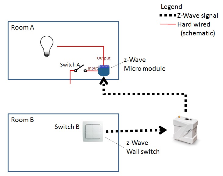
W.
In my understanding this is achievable for sure. Per your diagram, are you using Qubino Flush Relay as "micromodule"? if this is the case, the Inputs for the flush relays are usually not visible as devices and/or rule creator, only the actuator or output. In order to differentiate one from the other you have to make visible the inputs you are using so you can monitor the change of states. Regarding the wireless switch you can toggle the bulb using the rule creator and the action toggle, you don't need to trigger the inputs of the micro module, rather the relay itself.
W.
You made me curious and I double checked my Qubino Flush 2 relays (since I didn't have those inputs visible as devices). Looks like for this device there is no enpoint for the input, they just show for the output and for the meter, I looked into the manual and they don't specify any endpoint for I1 or I2, only Q1 and Q2...
This is for Qubino Flush Relay, look at endpoint two and three;
Endpoint 1
Device Class:
ZWAVEPLUS_INFO_REPORT_ROLE_TYPE_SLAVE_ALWAYS_0N
GENERIC_TYPE_SWITCH_BINARY
SPECIFIC_TYPE_POWER_SWITCH_BINARY
Command Classes:
COMMAND_CLASS_ZWAVEPLUS_INFO_V2
COMMAND_CLASS_VERSION_V2
COMMAND_CLASS_BASIC_V1
COMMAND_CLASS_SWITCH_ALL_V1
COMMAND_CLASS_SWITCH_BINARY_V1
COMMAND_CLASS_METER_V4
COMMAND_CLASS_ASSOCIATION_V2
COMMAND_CLASS_MULTI_CHANNEL_ASSOCIATION_V3
COMMAND_CLASS_ASSOCIATION_GRP_INFO_V2
COMMAND_CLASS_MARK
COMMAND_CLASS_BASIC_V1
Endpoint 2 (I2):
Device Class:
ZWAVEPLUS_INFO_REPORT_ROLE_TYPE_SLAVE_ALWAYS_0N
GENERIC_TYPE_SENSOR_NOTIFICATION
SPECIFIC_TYPE_NOTIFICATION_SENSOR
Command Classes:
COMMAND_CLASS_ZWAVEPLUS_INFO
COMMAND_CLASS_VERSION_V2
COMMAND_CLASS_SENSOR_BINARY
COMMAND_CLASS_BASIC
COMMAND_CLASS_NOTIFICATION_V5
COMMAND_CLASS_ASSOCIATION_V2
COMMAND_CLASS_MULTI_CHANNEL_ASSOCIATION_V3
COMMAND_CLASS_ASSOCIATION_GRP_INFO_V2
COMMAND_CLASS_MARK
COMMAND_CLASS_BASIC
Endpoint 3 (I3):
Device Class:
ZWAVEPLUS_INFO_REPORT_ROLE_TYPE_SLAVE_ALWAYS_0N
GENERIC_TYPE_SENSOR_NOTIFICATION
SPECIFIC_TYPE_NOTIFICATION_SENSOR
Command Classes:
COMMAND_CLASS_ZWAVEPLUS_INFO_V2
COMMAND_CLASS_VERSION_V2
COMMAND_CLASS_SENSOR_BINARY_V1
COMMAND_CLASS_BASIC_V1
COMMAND_CLASS_NOTIFICATION_V5
COMMAND_CLASS_ASSOCIATION_V2
COMMAND_CLASS_MULTI_CHANNEL_ASSOCIATION_V3
COMMAND_CLASS_ASSOCIATION_GRP_INFO_V2
COMMAND_CLASS_MARK
COMMAND_CLASS_BASIC_V1
This is for qubino flush sensor 2;
Root device:
Group 1: Lifeline group (reserved for communication with the main controller), 1 node allowed.
Group 2: basic on/off (triggered at change of the output Q1 state and reflecting its state) up to 16 nodes.
Group 3: switch binary report (triggered at change of the output Q1 state and reflecting its state) up to 16 nodes.
Group 4: power meter report (triggered at change of the output Q1 state) up to 16 nodes.
Group 5: basic on/off (triggered at change of the output Q2 state and reflecting its state) up to 16 nodes.
Group 6: switch binary report (triggered at change of the output Q2 state and reflecting its state) up to 16 nodes.
Group 7: power meter report (triggered at change of the output Q2 state) up to 16 nodes.
Group 8: multilevel sensor report (triggered at change of temperature sensor) up to 16 nodes.
End point 1:
Group 1: Lifeline group, 0 nodes allowed.
Group 2: basic on/off (triggered at change of the output Q1 state and reflecting its state) up to 16 nodes.
Group 3: switch binary report (triggered at change of the output Q1 state and reflecting its state) up to 16 nodes.
Group 4: power meter report (triggered at change of the output Q1 state and reflecting its state) up to 16 nodes.
End point 2:
Group 1: Lifeline group, 0 nodes allowed.
Group 2: basic on/off (triggered at change of the output Q2 state and reflecting its state) up to 16 nodes.
Group 3: switch binary report (triggered at change of the output Q2 state and reflecting its state) up to 16 nodes.
Group 4: power meter report (triggered at change of the output Q2 state and reflecting its state) up to 16 nodes.
End point 3:
Group 1: Lifeline group, 0 nodes allowed.
Group 2: multilevel sensor report (triggered at change of temperature sensor) up to 16 nodes.
Alberto, thanks for your comments. Seems I still have to look for a workaround, isn't it?
There are some options I was thinking about: since the flush 2 relays has 2 relays :-)... and the 2nd one is not used, I could hard wire both outputs in parallel to the bulb and then trigger output 1 with input 1 (and program a delay within the device parameter 11 e.g. to 5 minutes). Output 2 could then be triggered by switch B. But it's not the best solution because I also would like to switch off the light with switch A after it has been activated with switch B and vice versa ... (sigh...)
Any other ideas are welcome :-)
W.
I wouldn't hardwire in paralel the device, if you enable both outputs at the same time you might have an electrical problem.
Thinking about your current goal;
1. You can set a delay in the qubino module using parameter 12 or 13 depending of which output you want to turn OFF after a determined time. No rule required, just configuration.
2. Lets say you wire switch A to I1, this will Turn ON/OFF Q1 emulating I1 status, this is done automatically by the module, you don't need to create a rule for this, same applies to I2/Q2.
3. Using switch B you can set up a rule to Toggle the desired relay regardless of input status.
The only problem with this setup that I can think of is; if you turn ON the bulb from Switch A, I1=ON and Q1=ON, all good, then you decide to turn it OFF from switch B so you press switch B and Q1=OFF but I1 on switch A is ON (Q1=OFF, I1=ON). If you later decide to turn the bulb ON again from switch A you will have to press the button twice, first to set I1=OFF (Q1 stays OFF) and then again to set I1=ON (Q1 turns ON). This is better than nothing...
Hi Alberto,
The behaviour is not exactly as you described.
Line 1 = OK
Line 2 = OK
Line 3: when using switch B (via rule) to switch the bulb on, the delay is also applicable. The bulb will go OFF after delay.
Futhermore: I can always switch off the bulb with both switches, independantly from which switch has activated it... no double clicking required.
So I have to find out a way to bypass the delay. I could crate a rule for switch B that would reactive the bulb after every 10' for example for a few hours but then again I will probably not be able to switch off the bulb with switch A as it would be reactivated by the rule...
The current situation is not ideal, but I can live with it :-) So please don't take too much time to find a solution (unless you really want to ;-)
Thanks anyway!
W.
That seems weird, but I don't have any z-wave switch to make a test. Double clicking (in my theory) was going to be necessary to turn ON the bulb again from the wired switch after it was turned OFF from the z-wave switch. Try turning ON the bulb from the wired switch, then turn it OFF from the z-wave one, then try to turn it ON again from the wired one, if it works with one click then I'm missing something... anyway that's good for you.
Which delay you are talking about? parameter 11 is AUTO OFF DELAY, 12 is AUTO ON DELAY for relay 1 so one should not affect the other (I don't use those parameters so I never tested it before) or do you mean that the delay applies regardless of which switch you used to turn ON the switch? the second option you won't be able to bypass since it's parameter configuration but otherwise you don't have a way to know which switch you used to turn it ON, unless you create a "memory" using a virtual switch, virtual sensor or variable, and set it ON whenever the Z-wave switch changes state and the relay changes from OFF to ON. This "memory" would have to be turned OFF when the relay goes OFF, then you can get rid of the delay in the parameters and only apply the automatic turned OFF when you didn't used the z-wave switch.
Hi Alberto,
I turned on/off as you suggested and it reacts as I had described.
I am talking about the auto off delay. I don't see an auto on delay. The auto off delay does indeed work for either switches. (note I use the standard zwave Qubino module, not the zwave PLUS module. Maybe there is difference)
But your suggestion to use a virtual switch is something that might help. II could indeed trigger the state of the relay AND the action of the remote switch (B) and based on that result take different actions.
I'll probably try this in one of the coming days and keep this post updated.
Thanks!
I quickly checked:
There are indeed 2 types of Qubino Flush 2 Relays with different parameter settings/behaviour and different device & command classed (but I'm not really familiar with the meaning/use of those classes)
- ZWAVE PLUS: type ZMNHBD -- http://qubino.com/download/1029/
The Zwave PLUS-model has indeed both an auto ON and auto OFF delay parameter (11, 12, 13, 14), while the old version has only auto OFF parameters (11, 12)
I am using the "old" version.
Oh, I have the new one. Well it's good you don't need the double click thing. The virtual switch is the only way I can think of to solve this exactly how you want it, good luck!!
Oh, I have the new one. Well it's good you don't need the double click thing. The virtual switch is the only way I can think of to solve this exactly how you want it, good luck!!
Replies have been locked on this page!