

This object is in archive!
Fibaro RGBW Configuration to have 10V inputs
Need Answer
Itry different configurations but still no value in the meters.
Pleaseassist me with the right settings.
 The same question
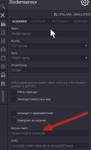
You can't vote. Please authorize!
No connection
Real-time notifications may not work
Hi Alex,
I am fighting with the same setting and saw that you have posted a more detailed overview how to configure the Fibaro RGBW controller. It had the title "A working setup with...". Unfortunately, the page somehow does not exist anymore. Could you repost, maybe in this thread or PM me the procedure and screenshots? THanks, Frank
I don't know where the text is either.I put the text again below:
A working setup with Zipato and Fibaro RGBW device as input and output device.
After a long time of try and error I figure out how I can get a working setup.
Follow the steps below:
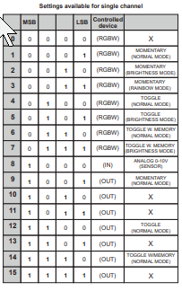
E Now you go to z-wave node management and press configure node See attach file (Step 2 e) The Zipato box / zipatile knows now the you RGBW device is a input and output device and gives you the options of four input.
If you want to change the standard location (and icon) of the RGBW input controller in your Zipato app or web interface follow the next steps
To show you that the device is working. See attach file (Step 6 and step 7)
Have fun with it and please give a sort response on this topic.
I don't know where the text is either.I put the text again below:
A working setup with Zipato and Fibaro RGBW device as input and output device.
After a long time of try and error I figure out how I can get a working setup.
Follow the steps below:
E Now you go to z-wave node management and press configure node See attach file (Step 2 e) The Zipato box / zipatile knows now the you RGBW device is a input and output device and gives you the options of four input.
If you want to change the standard location (and icon) of the RGBW input controller in your Zipato app or web interface follow the next steps
To show you that the device is working. See attach file (Step 6 and step 7)
Have fun with it and please give a sort response on this topic.
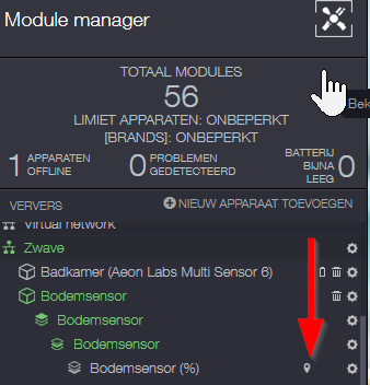
I think that's the way forward. I still have problems with variable these spontaneously lose their value and are then back to 0. one of these days I'm converting my setup to virtual meters. I can read it out and make a new decision. I also use virtual meters to check the threshold, for example, spraying is needed. The lower meter is the threshold. See image .
Would you like to share your calculation so others can learn or use it?
Hi Alex. Glad to share! So here is what I did:
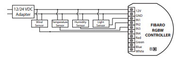
a. Connect a vegetronix VH400 with a Fibaro 441 (I used IN1): there is a description here for the wiring only (in German unfortunately): https://www.siio.de/bodenfeuchtigkeit-mit-dem-z-wave-fibaro-rgbw-controller-messen/
b. Add Fibaro 441 to Zipato
c. Follow the steps 1-6 set out in Alex's post above: you should now have a multilevel switch. For me I get decimal numbers for IN1.
d. Add a virtual meter and for value 1 use the unit % (see screenshot)
e. Take your Vegetronix probe and put it in a glass of water (100% humidity). Note the value (for me it was 51). Now take the probe out and dry it well (0% humidity). Note the value (for me it was 36).
f. The math part. I assume we have a linear relationship. The formular is y=(dy/dx)*x + a. The gradient is: dy=100 and dx=15: 100/15. We have two points for x,y: (0,36) and (100,51). One point is enough to determine the value for a: 0 = (100/15)*36 + a. This gives a value for a of -240. Now we have the formula for the linear slope, which is: y = (100/15)*x -240
g. back to Zipato rules: see screen shot with the formula. basically it triggers whenever there is a change in the value for IN1. I limit the value for IN1 in the IF part to be between 36 and 52 (a tad higher than the max level of 51 I found out) - like this I don't get crazy values in my virtual meter. When the value is in this bracket, then the above formula calculates value 1 (%) of my virtual meter
I am adding also a screen shot the result.
Works fine so far. I still need to understand what the limit value is for my soil humidity when I need to trigger the irrigation in the morning (e.g. when the soil gets too dry).
Hi Alex. Glad to share! So here is what I did:
a. Connect a vegetronix VH400 with a Fibaro 441 (I used IN1): there is a description here for the wiring only (in German unfortunately): https://www.siio.de/bodenfeuchtigkeit-mit-dem-z-wave-fibaro-rgbw-controller-messen/
b. Add Fibaro 441 to Zipato
c. Follow the steps 1-6 set out in Alex's post above: you should now have a multilevel switch. For me I get decimal numbers for IN1.
d. Add a virtual meter and for value 1 use the unit % (see screenshot)
e. Take your Vegetronix probe and put it in a glass of water (100% humidity). Note the value (for me it was 51). Now take the probe out and dry it well (0% humidity). Note the value (for me it was 36).
f. The math part. I assume we have a linear relationship. The formular is y=(dy/dx)*x + a. The gradient is: dy=100 and dx=15: 100/15. We have two points for x,y: (0,36) and (100,51). One point is enough to determine the value for a: 0 = (100/15)*36 + a. This gives a value for a of -240. Now we have the formula for the linear slope, which is: y = (100/15)*x -240
g. back to Zipato rules: see screen shot with the formula. basically it triggers whenever there is a change in the value for IN1. I limit the value for IN1 in the IF part to be between 36 and 52 (a tad higher than the max level of 51 I found out) - like this I don't get crazy values in my virtual meter. When the value is in this bracket, then the above formula calculates value 1 (%) of my virtual meter
I am adding also a screen shot the result.
Works fine so far. I still need to understand what the limit value is for my soil humidity when I need to trigger the irrigation in the morning (e.g. when the soil gets too dry).
Hi, Frank,
Thank you for your explanation. I have a similar description in Dutch see link:
https://www.robbshop.nl/domotica/projecten/je-tuin-in-topconditie
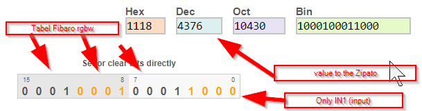
For the Hexadecimal Decimal Binary Octal Converter i use see link:
http://calc.50x.eu/
I have tested with different supply voltage 12V to 20V . There were no differences in maximum value 51%. Maximum value Vegetronix probe is 20V.
Assume that everyone will now get the set-up working with this explanation.
Hi, Frank,
Thank you for your explanation. I have a similar description in Dutch see link:
https://www.robbshop.nl/domotica/projecten/je-tuin-in-topconditie
For the Hexadecimal Decimal Binary Octal Converter i use see link:
http://calc.50x.eu/
I have tested with different supply voltage 12V to 20V . There were no differences in maximum value 51%. Maximum value Vegetronix probe is 20V.
Assume that everyone will now get the set-up working with this explanation.
Your article is very meaningful, the content is quite interesting and impressive, I hope in the near future you will have many interesting and meaningful articles to bring to readers.
fnafworld
Your article is very meaningful, the content is quite interesting and impressive, I hope in the near future you will have many interesting and meaningful articles to bring to readers.
fnafworld
Most interesting post
thanks for sharing
golf clash cheats
Most interesting post
thanks for sharing
golf clash cheats
Replies have been locked on this page!